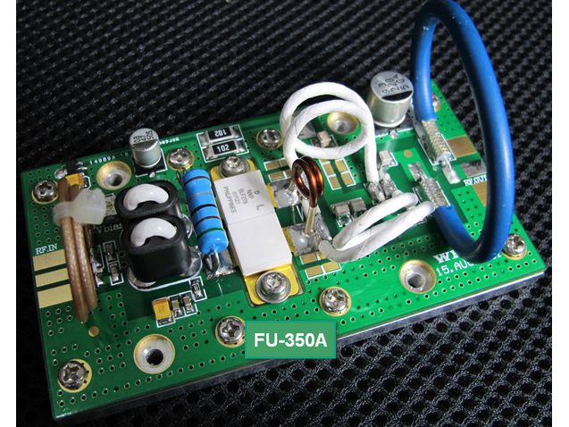
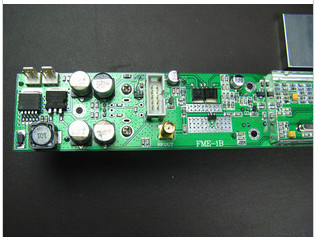
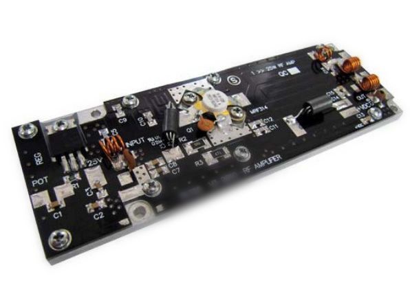
25W FM RF Power Amplifier Pallet 87.5MHz-108MHz Input 1.2W output 25W
25 W – FM Amplifier Pallet
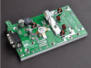
Designed for fm radio transmitter , Drivers
this amplifier incorporates microstrip
technology to enhance ruggedness
and reliability
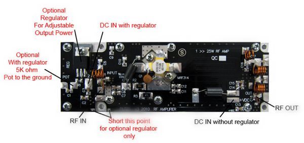
optional regulator on board
for output Power adjust
• 87.5 ÷ 108 MHz 1.2W input• 28 Volts
• Input/Output 50 Ω
• Pout : 25W min 32W max• Gain : 13 dB typ 14 db max
• Class A B
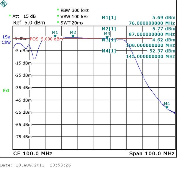
• Low pass filter on board
• Devices: MRF314 or equivalent
Designed for fm radio transmitter , Drivers
this amplifier incorporates microstrip
technology to enhance ruggedness
and reliability
optional regulator on board
for output Power adjust
• 87.5 ÷ 108 MHz 1.2W input• 28 Volts
• Input/Output 50 Ω
• Pout : 25W min 32W max• Gain : 13 dB typ 14 db max
• Class A B
• Low pass filter on board
• Devices: MRF314 or equivalent
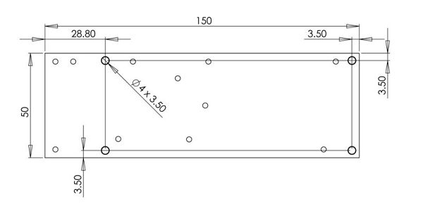
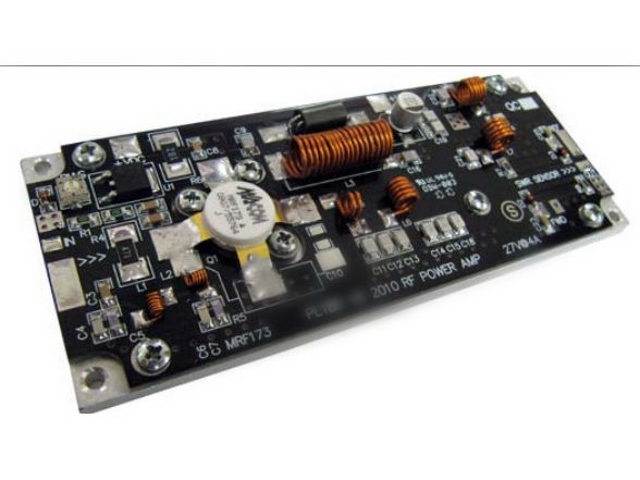
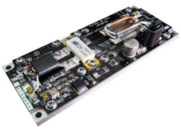
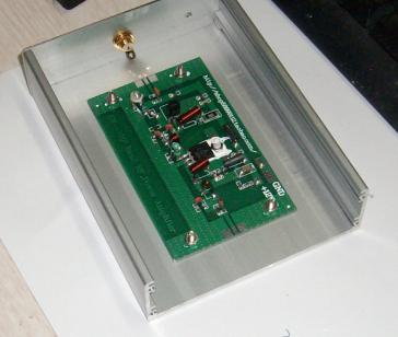
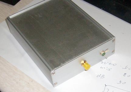
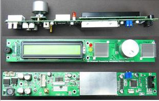
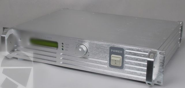
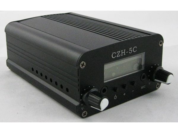
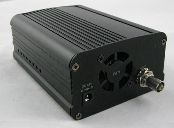
Dimension (L x W x H): 150 x 50 x 15mm [6" x 2" x 0.6"] This picture is a mere example, it does not bind the provided product
Vdc: Drain Voltage Supply:30V
Idc: Supply Current:3A
swr: Load Mismatch (all phase angles, Tc=40°C, Id=4A):10:1SWR
Pin: Input RF Power: 3W
Tstg: Storage Temperature Range -40 to +80 °C
Tc: Operating Temperature: +70°C
Idc: Supply Current:3A
swr: Load Mismatch (all phase angles, Tc=40°C, Id=4A):10:1SWR
Pin: Input RF Power: 3W
Tstg: Storage Temperature Range -40 to +80 °C
Tc: Operating Temperature: +70°C
ELECTRICAL SPECIFICATIONS (Base Plate T = 45 °C, 50Ω loaded, Vcc = 28 V @ 1.9A)
Operating Frequency Range: 86-109MHz
Fundamental Output Power: 25-35 W
Input Power: 1=1.2W
Power Gain (50W output): 13-14 db
Collector Efficiency (Load 50Ω):60-70 %
Input SWR: 1.5:1 2:1 SWR
F2 Second Harmonic: -60 ~ -70 dbc
F3 Third Harmonic: -55 ~ -65 dbc
Fundamental Output Power: 25-35 W
Input Power: 1=1.2W
Power Gain (50W output): 13-14 db
Collector Efficiency (Load 50Ω):60-70 %
Input SWR: 1.5:1 2:1 SWR
F2 Second Harmonic: -60 ~ -70 dbc
F3 Third Harmonic: -55 ~ -65 dbc
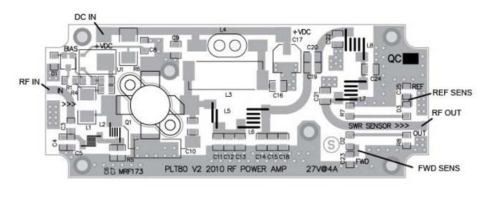
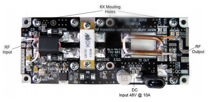
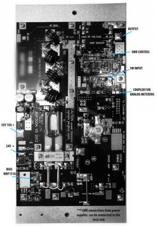
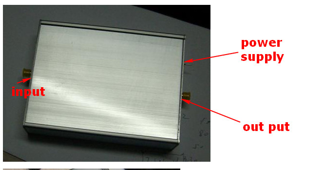
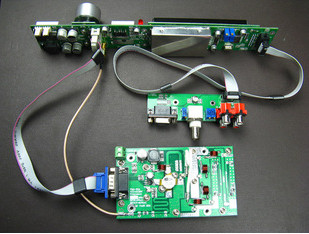
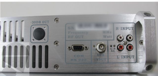
ELECTRICAL CONNECTIONS
Warning – Operating without antenna or dummy load (50ohm) can permanently damage to broadcast equipment.
Warning – Check the output connection before applying DC voltage to the module.
Warning – Operating without antenna or dummy load (50ohm) can permanently damage to broadcast equipment.
Warning – Check the output connection before applying DC voltage to the module.
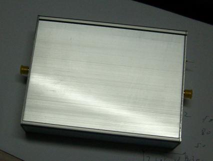
HEATSINK MOUNTING/HARDWARE
Warning – This module must be place on a heat sink that is at least 160X80X30 mm
If the module will be over heated above 50°C – Air fan should be applied to the heat sink.
Warning – Overheating can cause permanently damage to fm transmitter.
1.HEATSINK TOOLING
-Planarity: typical value 1μ
-Roughness: better than 0.05 mm
2.THERMAL COMPOUND
-Paste with silicones
-Thickness: optimum between 0.06 mm and 0.15 mm, on the whole back surface
of the amplifier.
3.SCREWS
-M3 hexagon socket head cap screws
-The recommended Torque is 12 Kg/cm for M3 type screws
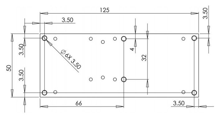
4.TIGHTENING ORDER
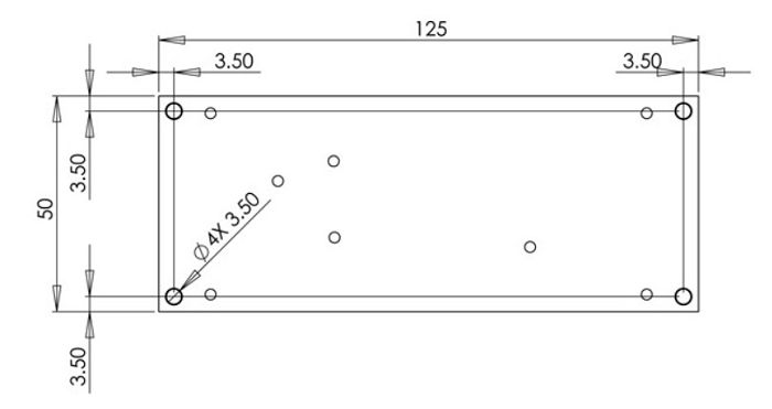
-See next figure: (all dimensions are in mm)
-Planarity: typical value 1μ
-Roughness: better than 0.05 mm
2.THERMAL COMPOUND
-Paste with silicones
-Thickness: optimum between 0.06 mm and 0.15 mm, on the whole back surface
of the amplifier.
3.SCREWS
-M3 hexagon socket head cap screws
-The recommended Torque is 12 Kg/cm for M3 type screws
4.TIGHTENING ORDER
-See next figure: (all dimensions are in mm)