2012年11月25日星期日

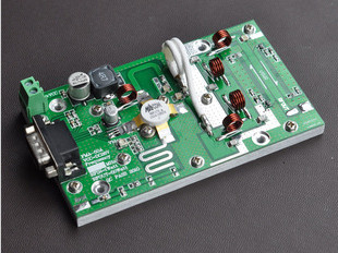
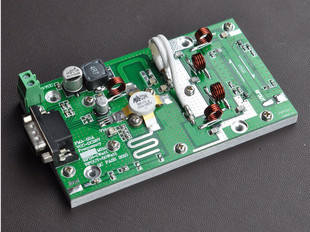
RFU25 - 25W FM RF Power Amplifier Pallet 87.5MHz-108MHz Input 1.2W output 25W


25W FM RF Power Amplifier Pallet 87.5MHz-108MHz Input 1.2W output 25W
25 W – FM Amplifier Pallet
Designed for fm radio transmitter , Drivers
this amplifier incorporates microstrip
technology to enhance ruggedness
and reliability
optional regulator on board
for output Power adjust
• 87.5 ÷ 108 MHz 1.2W input• 28 Volts
• Input/Output 50 Ω
• Pout : 25W min 32W max• Gain : 13 dB typ 14 db max
• Class A B
• Low pass filter on board
• Devices: MRF314 or equivalent
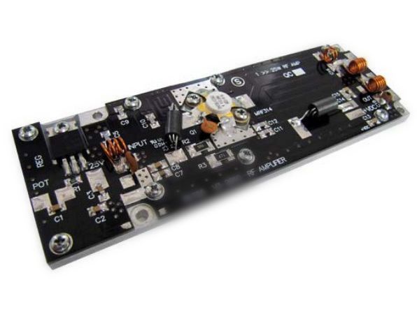
Dimension (L x W x H): 150 x 50 x 15mm [6" x 2" x 0.6"] This picture is a mere example, it does not bind the  provided product
Vdc: Drain Voltage Supply:30V 
Idc: Supply Current:3A 
swr: Load Mismatch (all phase angles, Tc=40°C, Id=4A):10:1SWR
Pin: Input RF Power: 3W
Tstg: Storage Temperature Range  -40 to +80  °C
Tc: Operating Temperature: +70°C
ELECTRICAL SPECIFICATIONS (Base Plate T = 45 °C, 50Ω loaded, Vcc = 28 V @ 1.9A)
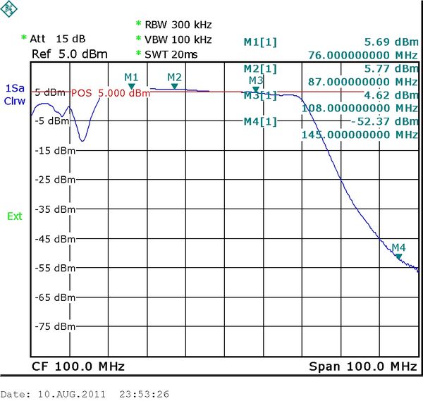
Operating Frequency Range: 86-109MHz 
Fundamental Output Power: 25-35 W 
Input Power: 1=1.2W
Power Gain (50W output): 13-14 db
Collector  Efficiency (Load 50Ω):60-70 %
Input  SWR: 1.5:1   2:1 SWR
F2 Second Harmonic: -60 ~ -70  dbc
F3 Third Harmonic: -55 ~ -65 dbc
ELECTRICAL CONNECTIONS
Warning – Operating without antenna or dummy load (50ohm) can permanently damage to broadcast equipment.
Warning – Check the output connection before applying DC voltage to the module.
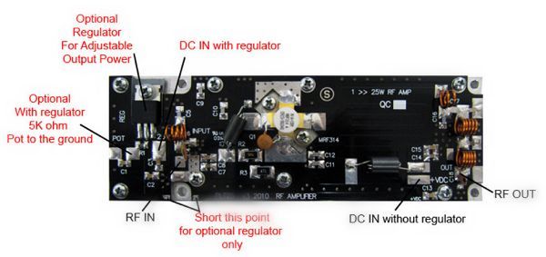

HEATSINK MOUNTING/HARDWARE
Warning – This module must be place on a heat sink that is at least 160X80X30 mm
If the module will be over heated above 50°C – Air fan should be applied to the heat sink.
Warning – Overheating can cause permanently damage to fm transmitter.
1.HEATSINK TOOLING 
-Planarity: typical value 1μ
-Roughness: better than 0.05 mm
2.THERMAL COMPOUND 
-Paste with silicones
-Thickness: optimum between 0.06 mm and 0.15 mm, on the whole back surface
of the amplifier.
3.SCREWS 
-M3 hexagon socket head cap screws
-The recommended Torque is 12 Kg/cm for M3 type screws
4.TIGHTENING ORDER 
-See next figure: (all dimensions are in mm)

RFU80 - 80W FM RF Power Amplifier Pallet 88MHz-108MHz Input 1.2W output 80W


RFU80 - 80W FM RF Power Amplifier Pallet 88MHz-108MHz Input 1.2W output 80W
80 W – FM Amplifier PalletDesigned for fm radio transmitter , Drivers
this amplifier incorporates microstrip technology
and MOSFET transistor to enhance ruggedness
and reliability.
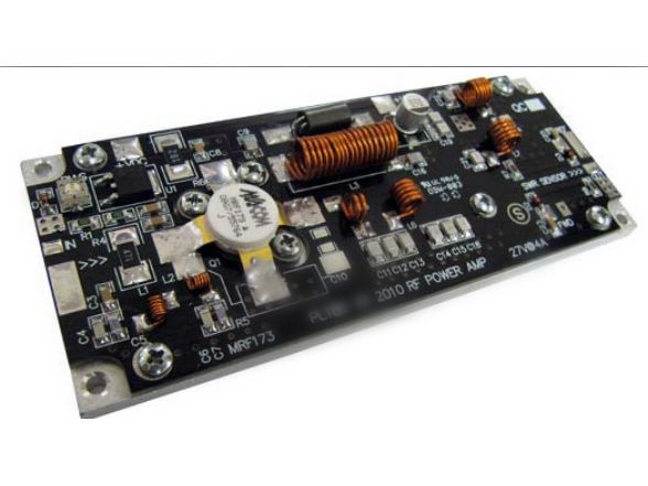
SWR SENSOR / LPF ON BOARD
• 87.5 ÷ 108 MHz
• 28 Volts
• Input/Output 50 Ω
• Pout : 50W min 80W max• Gain : 18 dB typ 19.5 db max
• Class B Id=2mA
• Low pass filter on board
• SWR sensor on board
• Devices: MRF173 or equivalent
Dimension (L x W x H): 125 x 50 x 15mm [5" x 2" x 0.6"]  This picture is a mere example, it does not bind the  provided product
ABSOLUTE MAXIMUM RATINGS (Device Flange T = 70 °C)
Vdc  Drain Voltage Supply:30V
Idc Supply Current:5A
swr  Load Mismatch (all phase angles, Tc=40°C, Id=4A):10:1SWR
Pin  Input  RF  Power:3W
Tstg  Storage Temperature Range: -40 to +80°C
Tc Operating Temperature:+70°C
ELECTRICAL SPECIFICATIONS (Base Plate T = 45 °C, 50Ω loaded, Vd = 28 V @3.8A)
Operating Frequency Range:86-109  MHzFundamental Output Power:55W -80 W 
Input Power:1.2WPower Gain (50W output):18-19.5 db
Drain Efficiency (Load 50Ω):60-70  %
Input  SWR:  3:1 2:1 SWR
F2 Second Harmonic: -60 to -70  dbc
F3 Third Harmonic: -55 to -65 dbc
ELECTRICAL CONNECTIONS
Warning – Operating without antenna or dummy load (50ohm) can permanently damage to the low power fm.
Warning – Check the output connection before applying DC voltage to the module.
HEATSINK MOUNTING/HARDWARE
Warning – This module must be place on a heat sink that is at least 150X80X40 mm
If the module will be over heated above 50°C – Air fan should be applied to the heat sink.
Warning – Overheating can cause permanently damage to the power transistor.
1.HEATSINK TOOLING
-Planarity: typical value 1μ
-Roughness: better than 0.05 mm
2.THERMAL COMPOUND
-Paste with silicones
-Thickness: optimum between 0.06 mm and 0.15 mm, on the whole back surface
of  fm amplifier.
3.SCREWS
-M3 hexagon socket head cap screws
-The recommended Torque is 12 Kg/cm for M3 type screws
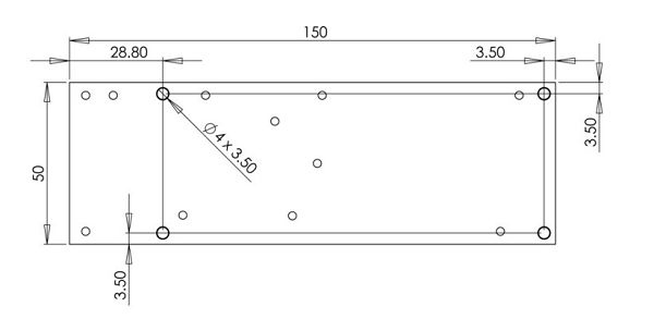
4.TIGHTENING ORDER
-See next figure: (all dimensions are in mm)
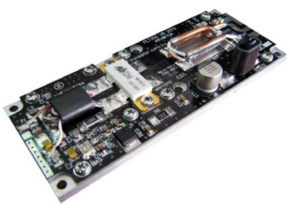
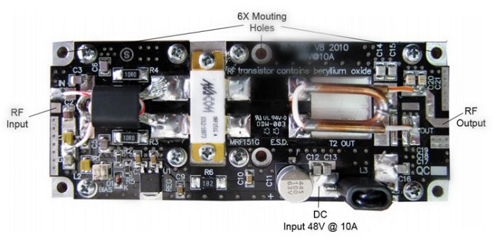
RFU300 - 300W FM RF Power Amplifier Pallet 88MHz-108MHz Input 5W output 300W


RFU300 - 300W FM RF Power Amplifier Pallet 88MHz-108MHz Input 5W output 300W
Designed for  fm radio transmitter 
this amplifier incorporates microstrip
technology to enhance ruggedness
and reliability
MOSFET TECHNOLOGY
• 87.5 ÷ 108 MHz 5W input
• 48 Volts
• Input/Output 50 Ω
• Pout : 250W min 320W max• Gain : 19 dB typ
• Class B Bias ADJ
• Low pass filter on board
• Devices: MRF151G or equivalent
300W – FM Amplifier Pallet
Dimension (L x W x H): 150 x 50 x 15mm [5" x 2" x 0.6"]
This picture is a mere example, it does not bind the
provided product
ABSOLUTE MAXIMUM RATINGS (Device Flange T = 70 °C)
Vdd  Drain Voltage Supply: 52V
Idc Supply Current: 12A 

swr  Load Mismatch (all phase angles, Tc=40°C, Id=10A): 3:1SWR
Pin Input Power: 10W
Tstg  Storage Temperature Range: -30 to +100 °C
Tc  Operating Temperature:  -10 to +70  °C
ELECTRICAL SPECIFICATIONS (Base Plate T = 45 °C, 50Ω loaded, Vdd = 48 V @ 10A)
Operating Frequency Range: 86 to 109  MHz
Fundamental Output Power: 280 300 320 WInput Power: 5 W 
Power Gain (300W output):  17.5 19db
Drain  Efficiency (Load 50Ω):  65  75 %
Input  SWR :  1.5:1 1.7:1 SWR
Insertion Phase Variation (Unit to Unit ):  -/+ 10 dgrees
Power Gain Variation (Unit to Unit):  -/+ 1 db
F2 Second Harmonic: -30 Db
F3 Third Harmonic:  -35 db
ELECTRICAL CONNECTIONS
Warning – Operating without antenna or dummy load (50ohm) can permanently damage to the best fm transmitter.
Warning – Check the output connection before applying DC voltage to the module.
HEATSINK MOUNTING/HARDWARE
Warning – This module must be place on a heat sink that is at least 160X80X30 mm
If the module will be over heated above 50°C – Air fan should be applied to the heat sink.
Warning – Overheating can cause permanently damage to low power fm.
1.HEATSINK TOOLING
-Planarity: typical value 1μ
-Roughness: better than 0.05 mm
2.THERMAL COMPOUND
-Paste with silicones
-Thickness: optimum between 0.06 mm and 0.15 mm, on the whole back surface
of the amplifier.
3.SCREWS
-M3 hexagon socket head cap screws
-The recommended Torque is 12 Kg/cm for M3 type screws
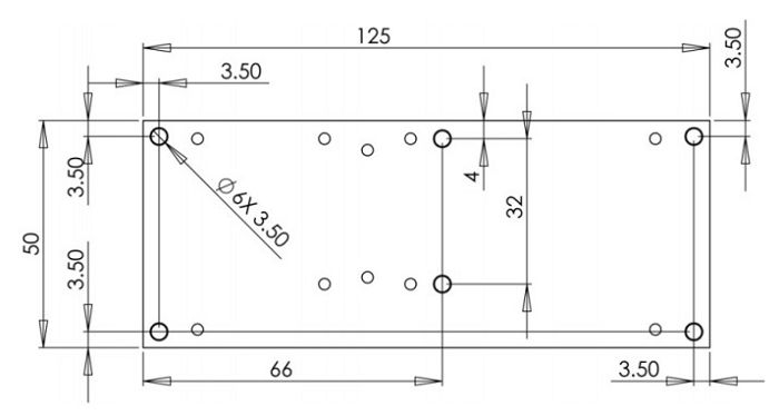
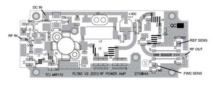
4.TIGHTENING ORDER
-See next figure: (all dimensions are in mm)
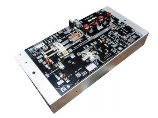
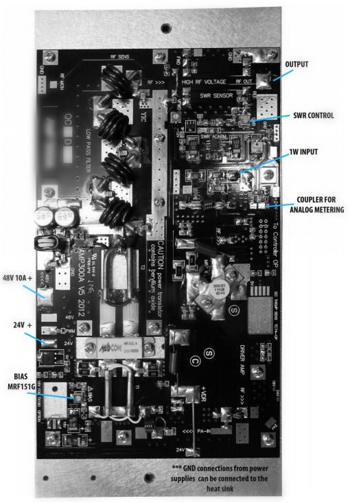
AMU300 - 300W FM RF Power Amplifier Module 88MHz-108MHz Input 2W output 300W


AMU300 - 300W  fm transmitter kits  Amplifier Module 88MHz-108MHz Input 2W output 300W
300 W – FM Amplifier Module
Designed for fm radio transmitter ,
this amplifier incorporates micro strip technology
and MOSFET transistor to enhance ruggedness
and  reliability.
SWR SENSOR / SWR PROTECTION
/ LPF ON BOARD
• 87.5 ÷ 108 MHz
• 48 Volts and 24V required
• Input / Output 50 Ω
• Gain: 18 dB typ 19.5 db max
• Class B Id=2mA
• Low pass filter on board
• SWR sensor on board
• Devices: MRF151 or equivalent + MRF314 (input section)
Dimension (L x W x H): 125 x 50 x 15mm [5” x 2” x 0.6”]
This picture is a mere example, it does not bind the
provided product
ABSOLUTE MAXIMUM RATINGS (Device Flange T = 70 °C)
Vdc  Drain Voltage Supply:52V
Idc Supply Current:12A
Vswr  Load Mismatch (all phase angles, Tc=40°C, Id=4A):3:1 Vswr
Pin  Input  RF  Power: 2W
Tstg  Storage Temperature Range : -40 to +80  °C
Tc Operating Temperature: +70  °C
ELECTRICAL SPECIFICATIONS (Base Plate T = 45 °C, 50Ω loaded, Vd = 28 V)
Operating Frequency Range: 86 ~ 109  MHz
Fundamental Output Power: 280 ~ 320  W
Input Power:  1~ 2W
Power Gain (300W output): 17.5 ~ 19db
Drain Efficiency (Load 50Ω): 60 ~ 65 %
Input VSWR: 1.5:1     1.7:1 Vswr
F2 Second Harmonic:  -70 ~ -80  dbc
F3 Third Harmonic :  -60 ~ -65 dbc
ELECTRICAL CONNECTIONS
Warning – Operating without antenna or dummy load (50ohm) can permanently damage to the  long range fm transmitter.
Warning – Check the output connection before applying DC voltage to the module.

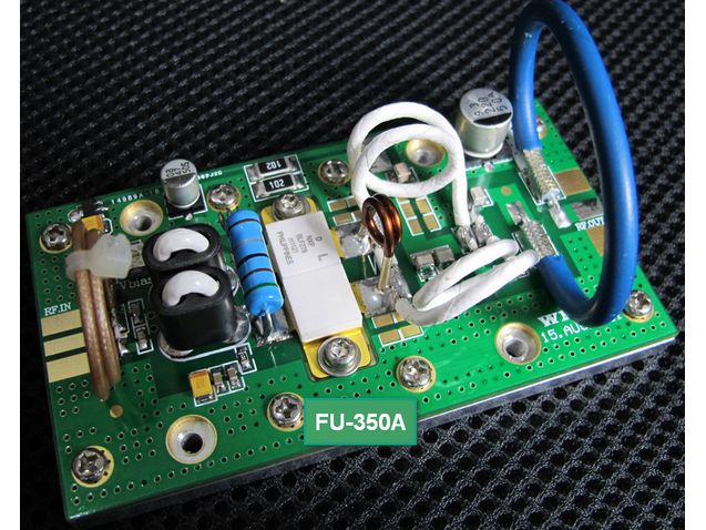
FU-350A 350W 300W FM power amplifier pallet module75Mhz - 110Mhz input 3W output 350W


FU-350A 350W  FM exciter  amplifier pallet module 75Mhz - 110Mhz input 3W output 350W
We will send the product to you with DHL , It can arrive within 7days to every country every place in the world.

Application: This product is mainly used for  rf transmitter  equipment production and assembly.
Performance characteristics:
The entire board with blue double-sided high-frequency epoxy PCB. Excellent high frequency characteristics of beautiful appearance.
 fm radio broadcast transmitter  structure includes an RF amplifier circuit.
The RF amplifier consists of well-known manufacturers NXP BLF278. Amplifier input power of 3.5W, the power amplifier output of 350 watts.
Technical parameters:
Power supply voltage: 48 ~ 50V
Operating Current: ≤ 11A
Efficiency: 68%
Frequency Range: 85MHz ~ 110MHz (maximum range 75MHz ~ 110Mhz)
Bandwidth: 35MHz
Gain: 19 in dBm
Input power: ≤ 3.5 watts, 4.5 watts maximum input
Output power: 350 watts (to adjust the input power can change the output power).
Harmonic Suppression: -65 dB
Flatness: <1 dBm
Operating temperature: -20 ℃ ~ 45 ℃
Duty: Continuous work
PCB Dimensions: Length 102MM * 35MM * 57MM * thick, wide
The other specifications of the amplifier, please contact us atsky@cantonmade.com

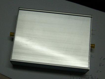
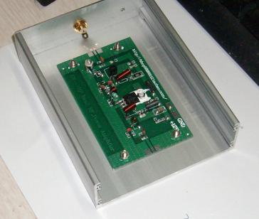
8W FM power amplifier 88-108MHz input 10mW output 7--8W


FM power amplifier  88-108MHz input 10mW  output 7--8W
This is the amplifier for the broadcasting transmitter power amplifier
As long as the input power of 10MW can be output 7 - 8W
Very clean FM signal
The circuit uses two power amplifiers,
Using of winding inductance and improve the circuit Q
Usingof broadband matching circuits
Operating frequency perfect cover 88-108MHZ
Using 12 - 13.8V DC power supply
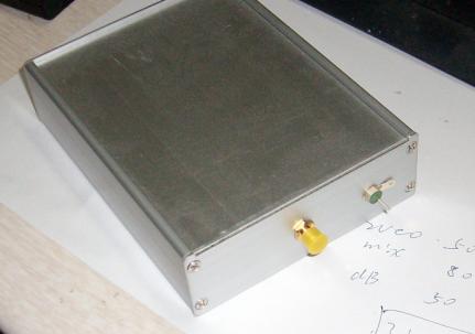
The circuit is mounted on the aluminum 2MM case, good signal and  radio broadcast transmitter  frequency interference shielding, so that your front-end circuit can be good to avoid any interference!
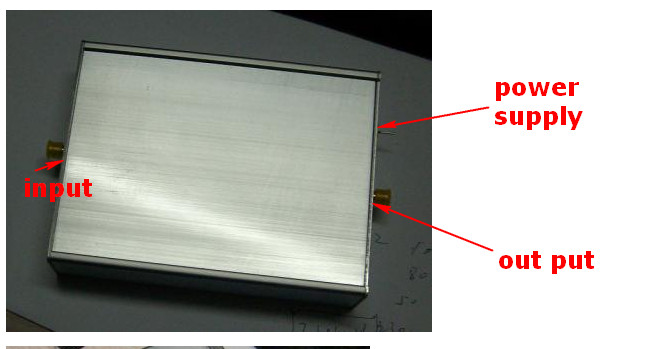
Amplifier output and input are using 50 ohm SMA connectors,  broadcast equipment  supply through the use of special high-frequency capacitance-core!

2012年11月20日星期二

RFU300 - 300W FM RF Power Amplifier Pallet 88MHz-108MHz Input 5W output 300W


RFU300 - 300W fm transmission Power Amplifier Pallet 88MHz-108MHz Input 5W output 300W
Designed for FM radio transmitters
this amplifier incorporates microstrip
technology to enhance ruggedness
and reliability
MOSFET TECHNOLOGY
• 87.5 ÷ 108 MHz 5W input
• 48 Volts
• Input/Output 50 Ω
• Pout : 250W min 320W max• Gain : 19 dB typ
• Class B Bias ADJ
• Low pass filter on board
• Devices: MRF151G or equivalent
300W – rf transmitter Pallet
Dimension (L x W x H): 150 x 50 x 15mm [5" x 2" x 0.6"]
This picture is a mere example, it does not bind the
provided product
 ABSOLUTE MAXIMUM RATINGS (Device Flange T = 70 °C)
Vdd  Drain Voltage Supply: 52V 
Idc Supply Current: 12A 

swr  Load Mismatch (all phase angles, Tc=40°C, Id=10A): 3:1SWR
Pin Input Power: 10W
Tstg  Storage Temperature Range: -30 to +100 °C
Tc  Operating Temperature:  -10 to +70  °C
ELECTRICAL SPECIFICATIONS (Base Plate T = 45 °C, 50Ω loaded, Vdd = 48 V @ 10A)
Operating Frequency Range: 86 to 109  MHz
Fundamental Output Power: 280 300 320 W Input Power: 5 W 
Power Gain (300W output):  17.5 19db
Drain  Efficiency (Load 50Ω):  65  75 %
Input  SWR :  1.5:1 1.7:1 SWR
Insertion Phase Variation (Unit to Unit ):  -/+ 10 dgrees
Power Gain Variation (Unit to Unit):  -/+ 1 db
F2 Second Harmonic: -30 Db
F3 Third Harmonic:  -35 db
ELECTRICAL CONNECTIONS
Warning – Operating without antenna or dummy load (50ohm) can permanently damage to the RF powerwhat is radio transmitter
Warning – Check the output connection before applying DC voltage to the module.
HEATSINK MOUNTING/HARDWARE
Warning – This module must be place on a heat sink that is at least 160X80X30 mm
If the module will be over heated above 50°C – Air fan should be applied to the heat sink.
Warning – Overheating can cause permanently damage to the power transistor.

1.HEATSINK TOOLING
-Planarity: typical value 1μ
-Roughness: better than 0.05 mm
2.THERMAL COMPOUND
-Paste with silicones
-Thickness: optimum between 0.06 mm and 0.15 mm, on the whole back surface
of the amplifier.
3.SCREWS
-M3 hexagon socket head cap screws
-The recommended Torque is 12 Kg/cm for M3 type screws 
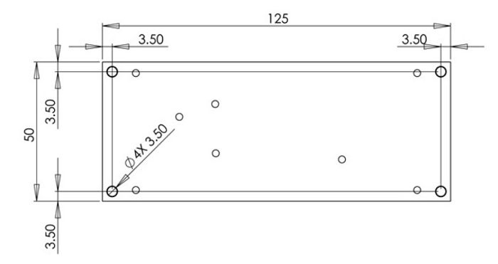
4.TIGHTENING ORDER
-See next figure: (all dimensions are in mm)
AMU300 - 300W FM RF Power Amplifier Module 88MHz-108MHz Input 2W output 300W


AMU300 - 300W FM RF Power Amplifier Module 88MHz-108MHz Input 2W output 300W
300 W – fm transmit Module
Designed for radio broadcast transmitter,
this amplifier incorporates micro strip technology
and MOSFET transistor to enhance ruggedness
and  reliability.
SWR SENSOR / SWR PROTECTION 
/ LPF ON BOARD

• 87.5 ÷ 108 MHz
• 48 Volts and 24V required
• Input / Output 50 Ω
• Gain: 18 dB typ 19.5 db max
• Class B Id=2mA
• Low pass filter on board
• SWR sensor on board
• Devices: MRF151 or equivalent + MRF314 (input section)
Dimension (L x W x H): 125 x 50 x 15mm [5” x 2” x 0.6”]
This picture is a mere example, it does not bind the
provided product
ABSOLUTE MAXIMUM RATINGS (Device Flange T = 70 °C)
Vdc  Drain Voltage Supply:52V
Idc Supply Current:12A
Vswr  Load Mismatch (all phase angles, Tc=40°C, Id=4A):3:1 Vswr
Pin  Input  RF  Power: 2W
Tstg  Storage Temperature Range : -40 to +80  °C
Tc Operating Temperature: +70  °C
ELECTRICAL SPECIFICATIONS (Base Plate T = 45 °C, 50Ω loaded, Vd = 28 V)
Operating Frequency Range: 86 ~ 109  MHz
Fundamental Output Power: 280 ~ 320  W
Input Power:  1~ 2W
Power Gain (300W output): 17.5 ~ 19db
Drain Efficiency (Load 50Ω): 60 ~ 65 %
Input VSWR: 1.5:1     1.7:1 Vswr
F2 Second Harmonic:  -70 ~ -80  dbc
F3 Third Harmonic :  -60 ~ -65 dbc
ELECTRICAL CONNECTIONS
Warning – Operating without antenna or dummy load (50ohm) can permanently damage to the RF power transistor.
Warning – Check the output connection before applying DC voltage to the fm modulator.


FU-350A 350W 300W FM power amplifier pallet module75Mhz - 110Mhz input 3W output 350W


FU-350A 350W rds fm transmitter pallet module 75Mhz - 110Mhz input 3W output 350W
We will send the product to you with DHL , It can arrive within 7days to every country every place in the world.


 Application: This product is mainly used forradio station equipment production and assembly.
Performance characteristics:
    The entire board with blue double-sided high-frequency epoxy PCB. Excellent high frequency characteristics of beautiful appearance.
    The board structure includes an fm amplifier circuit.
    The RF amplifier consists of well-known manufacturers NXP BLF278. Amplifier input power of 3.5W, the power amplifier output of 350 watts.
Technical parameters:
    Power supply voltage: 48 ~ 50V
    Operating Current: ≤ 11A
    Efficiency: 68%
    Frequency Range: 85MHz ~ 110MHz (maximum range 75MHz ~ 110Mhz)
    Bandwidth: 35MHz
    Gain: 19 in dBm
    Input power: ≤ 3.5 watts, 4.5 watts maximum input
    Output power: 350 watts (to adjust the input power can change the output power).
    Harmonic Suppression: -65 dB
    Flatness: <1 dBm
    Operating temperature: -20 ℃ ~ 45 ℃
    Duty: Continuous work
    PCB Dimensions: Length 102MM * 35MM * 57MM * thick, wide
    The other specifications of the amplifier, please contact us atsky@cantonmade.com


8W FM power amplifier 88-108MHz input 10mW output 7--8W


fm amplifier  88-108MHz input 10mW  output 7--8W
This is the amplifier for the radio broadcast transmitter power amplifier
As long as the input power of 
10MW can be output 7 - 8WVery clean FM signal
The circuit uses two power amplifiers, 
Using of winding inductance and improve the circuit Q
Usingof broadband matching circuits  
Operating frequency perfect cover 88-108MHZUsing 12 - 13.8V DC power supply
The circuit is mounted on the aluminum 2MM case, good signal and fm radio transmitter frequency interference shielding, so that your front-end circuit can be good to avoid any interference!
Amplifier output and input are using 50 ohm SMA connectors, power supply through the use of special high-frequency capacitance-core!

2012年11月7日星期三

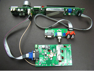
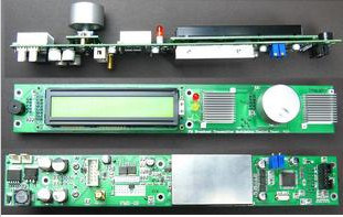
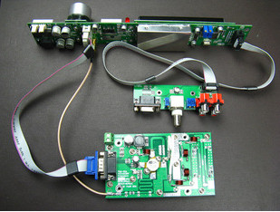
FSN-150 0-150W radio broadcast station FM transmitter PCB KITS


0-150W radio broadcast station fm transmitter kits

- A Kind Reminder: This is a kit and skilled assembly is required.
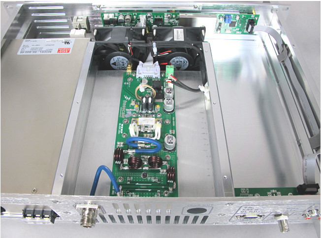
  - The Kit includes an amplifier board, a control panel board, an interface board and connection cables. 
  - Power adjustable: 0-150 watts
  - LCD displays working frequency, volume, temperature, forward power, reflected power and SWR, Single knob operation.
  - Automatic power control maintaining the output at any preset level Provided with SWR protection function and temperature protection, raise alarm prompts once meet any trouble while working.
     
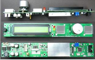
(1) Control panel board
  - It includes fm modulator circuit, user interface circuit, RF drive circuit, fan control circuit, auto power control circuit.
  - The RF output of this board is 1 watt.
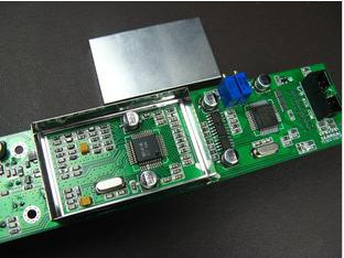
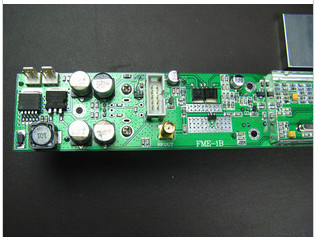
(2) Amplifier board
  - The amplifier circuit includes SD2931 power amplifier circuit, power and SWR measuring circuit, digital temperature detection circuit.               
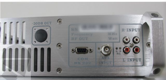
(3) Interface Board
  - Dual stereo audio input interface.
  - RS232 port (for Program debug, optional).
  - AUX interface.
  - Signal input level preset potentiometer.
(4) Connection cables
  - Connect control board with amplifier board cable.
  - Connect control board with interface board cable.
  - RF cable: connect control board with the final stage amplifying board.
  - Fool-proofing designed by color with IDC interface.
If you need the power supply for this 150W FM Transmitter PCB KIT, please click here

TECHNICAL SPECIFICATIONS:
  - Power supply voltage: DC 48V
  - Power Output: 0 to 150Watt adjustable (step 1W) 
  - Frequency range: 87.5-108 MHz
  - Frequency Step: 0.1MHZ 
  - Operating Current: Less than 6A 
  - Input power: Less than 1 watt
  - Harmonic suppression: -65 dBc 
  - Operating temperature: -10 ℃ ~ 50 ℃ 
  - Frequency stability: ± 10 ppm (-10  ° C to +60 ° C ) 
  - Frequency Response: 50 - 15000Hz 
  - SNR: More than 50dB 
  - Distortion: less than 0.5% 
  - Parasitic amplitude modulation: Less than 0.2% 
  - Frequency deviation: Less than ±75KHz 
  - Modulation Mode: WFM 
  - fm transmission Signal: FM Stereo or Mono 
  - Tuning Design: Stable PLL Technology 
  - Audio Input Level: -15db Max: -30db 
  - Stereo Separation: More than 40db 
  - Output Impedance: 50 ohm 
  - Amplifier PCB Size: 160mm(L) * 70MM(W) * 8MM(T)
PACKAGE INCLUDES:
  - Amplifier board *1
  - Control panel board *1
  - Interface board *1
  - Connection cable *1

FSN-801 0-80W radio broadcast station FM transmitter PCB KITS


FSN-801 0-80W radio broadcast station best fm transmitter PCB KITS
FEATURES:
  - A Kind Reminder: This is a kit and skilled assembly is required.
  - The Kit includes an amplifier board, a control panel board, an interface board and connection cables. 
  - Power adjustable: 0-80 watts
  - LCD displays working frequency, volume, temperature, forward power, reflected power and SWR, Single knob operation.
  - Automatic power control maintaining the output at any preset level Provided with SWR protection function and temperature protection, raise alarm prompts once meet any trouble while working.
     
(1) Control panel board
  - It includes FM modulation circuit, user interface circuit, RF drive circuit, fan control circuit, auto power control circuit.
  - The RF output of this board is 1 watt.
(2) Amplifier board
  - The amplifier circuit includes MRF173 power amplifier circuit, power and SWR measuring circuit, digital temperature detection circuit.               
(3) Interface Board
  - Dual stereo audio input interface.
  - RS232 port (for Program debug, optional).
  - AUX interface.
  - Signal input level preset potentiometer.
(4) Connection cables
  - Connect control board with fm amplifier board cable.
  - Connect control board with interface board cable.
  - RF cable: connect control board with the final stage amplifying board.
  - Fool-proofing designed by color with IDC interface.
If you want to the power supply for the 80W fm broadcast transmitter PCB KIT , please click here

TECHNICAL SPECIFICATIONS:
  - Power supply voltage: DC 28V
  - Power Output: 0 to 80Watt adjustable (step 1W) 
  - Frequency range: 87.5-108 MHz
  - Frequency Step: 0.1MHZ 
  - Operating Current: Less than 6A 
  - Input power: Less than 1 watt
  - Harmonic suppression: -65 dBc 
  - Operating temperature: -10 ℃ ~ 50 ℃ 
  - Frequency stability: ± 10 ppm (-10  ° C to +60 ° C ) 
  - Frequency Response: 50 - 15000Hz 
  - SNR: More than 50dB 
  - Distortion: less than 0.5% 
  - Parasitic amplitude modulation: Less than 0.2% 
  - Frequency deviation: Less than ±75KHz 
  - Modulation Mode: WFM 
  - Transmission Signal: FM Stereo or Mono 
  - Tuning Design: Stable PLL Technology 
  - Audio Input Level: -15db Max: -30db 
  - Stereo Separation: More than 40db 
  - Output Impedance: 50 ohm 
  - Amplifier PCB Size: 120mm(L) * 70MM(W) * 8MM(T)
PACKAGE INCLUDES:
  - Amplifier board *1
  - Control panel board *1
  - Interface board *1
  - Connection cable *1


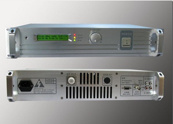
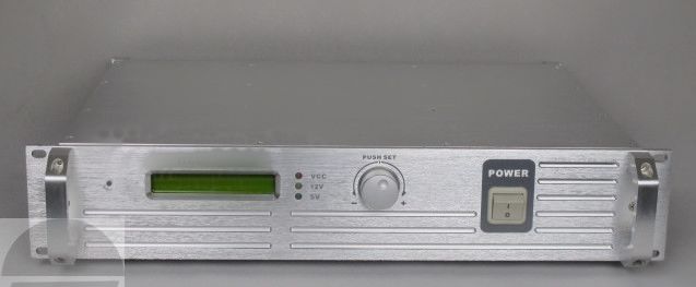
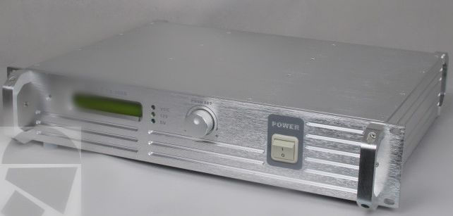
80W 2U FSN-801 Professional FM Broadcast Radio Transmitter 87.5-108 MHz cover 5KM-15KM


80W 2U FSN-801 Professionalradio broadcast equipment87.5-108 MHz
The  is an ultra compact size 87.5-108 MHz 80W best fm transmitter , high efficiency, fully solid state FM-modulated transmitter of 150W rated power. With advanced self protection and full digital front panel control features, advanced fm broadcast transmitter Technology.
Features:
-Frequency range: 87.5-108 MHz, 10 KHz/Step
-Modulation: FM, ±75 KHz peak deviation
-Frequency stability: <±100 Hz
-RF output power: 0 to 80W ±0.5 dB
-Max reflected power: 5 W
-Harmonic suppression: <-65 dBC
-RF output impedance: 50 Ω
-RF output connector: N type -female
-Audio/MPX input level: -10 to +13 dBm @±75 KHz deviation
-Audio/MPX input impedance: 10 KΩ / 600 Ω, Balanced / unbalanced
-Audio input connector: XLR-female
-AUX / MPX input level: -10 to +13 dBm @±75 KHz deviation
-AUX channel input impedance: 10 KΩ
-MPX and AUX input connector: BNC-female
-Pre-emphasis: 0 / 50 / 75 us
-S/N ratio Mono: >73 dB (20 to 20 KHz)
-S/N ratio Stereo: >68 dB (20 to 15 KHz)
-Distortion: <0.05% THD @± 75 KHz dev.
<0.2% THD @± 150 KHz dev. (limiter threshold > 150 KHz)
-Stereo crosstalk: >60 dB (100 to 5 KHz)
>50 dB (20 to 15 KHz) int. MPX encoder
>60 dB with ext. MPX encoder
-Audio channel frequency response: 20 to 15 KHz ± 0.15 dB
-MPX input frequency response: 10 to 100 KHz ± 0.15 dB
-AUX input frequency response: 10 to 100 KHz ± 0.15 dB
-Mains power supply requirements: 90~264VAC; 127~370VDC, Full range universal input
-Operating temperature range: -10 to 45 ℃
-Weight: 10 Kg
General features:

- Professional stereo sound with excellent separation
- Standard 19″ 2H rack, clean design and high quality manufacturing
- Low distortion and good Signal/Noise ratio
- Modular construction, internal boards can be replaced one by one
- Built-in CPU system for controlling and monitoring
- Advanced TEMP protection – SWR protection
- In our opinion the best quality/price ratio possible.


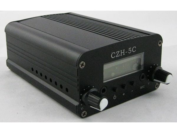
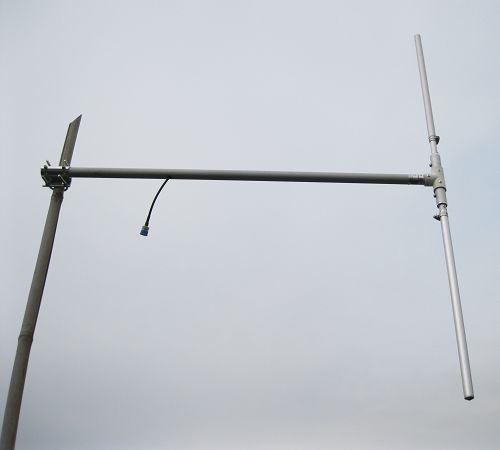
5W CZH-5C FM stereo PLL broadcast radio transmitter 88MHz -108MHz + DP100 dipole Antenna + Powersupply Kit cover 900M-3.5KM


5W CZH-5C FM stereo PLL fm broadcast transmitter 88MHz -108MHz + DP100 1/2 wave dipole Antenna + Powersupply fm transmitter kits cover 900M-3.5KM
Easy Build your own radio transmitter Station!
Just plug it , and you're on the air!
This is a kitset ,not need to buy any other ,Just plus it .
The price 165USD already include the shipping cost to all the countries in the word.
Features :
    * Phase Lock Loop (PLL) System
    * Easily choose your frequency LCD and buttons
    * Freq range :88MHz~108MHz
    * Power :5w
    * Ripple or harmonic waves: <= -60dB
    * Tuning Step : 100khz
    * Stability of Frequency: ±5ppm Less than 10ppm ( better system)
    * Freq. Response:  -55dB(100~5000Hz); -45dB(5000 ~ 15000Hz )
    * Audio Input Connector: 3.5mm headphone connector
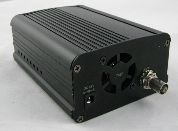
    * BNC Type antenna output
    * Reduced harmonic ( clean signal )
Package Include:
    * 1 X 5W CZH-5C FM transmitter
    * 1 X DP100 1/2 Wave dipole antenna 
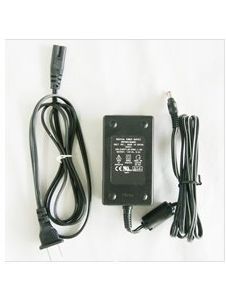
    * 1 X  power supply
    * 1X audio cable
If you have any question ,Please feel free to tell me :sky@cantonmade.com

<-------------------------- PHOTO-------------------------->